
GeoThrust is a unique 2D/3D surface seismic data analysis system developed by GeoTomo. Drs. Oz Yilmaz and Jie Zhang designed and supervised the development of the software package. GeoThrust combines advanced near-surface imaging techniques with innovative subsurface imaging strategies, and presents a powerful solution to difficult earth imaging problems. It is particularly applicable to areas with complex structures associated with overthrust tectonics and complex near-surface with irregular topography. GeoThrust is designed to obtain an accurate earth model and image in time and depth. Even data recorded with irregular geometry in areas with rough topography, complex near-surface, and complex subsurface are handled by GeoThrust. It has uncompromisingly high technical specifications for data analysis and quality control, but is easy to use.
Distinctively Unique Features :
- The near-surface model is estimated by nonlinear tomography applied to first arrival times and resolves lateral and vertical variations.
- GeoThrust performs subsurface velocity estimations, modeling, and imaging from topography, not from a flat datum, based on RMS and interval velocities estimated at reflector positions, not at reflection positions.
- GeoThrust near-surface modeling workflow allows to derive image-based statics without first-break picks and with the capability in handling the velocity inversion.
- GeoThrust imaging in time and depth are both performed by prestack Kirchhoff and wave equation migration algorithms with uncompromising accuracy and fidelity.
- GeoThrust 3D workflow scans both RMS velocities and the anisotropy parameter for enhanced 3D prestack time imaging of the v(z) media.
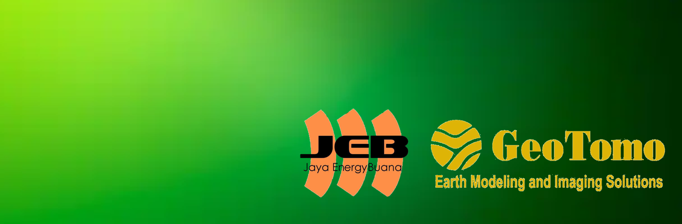
- The system provides the analyst with powerful interactive tools to perform quality control of geometry and for appropriate specification of signal processing parameters, and picking RMS and interval velocities.
- The system is based on a workflow architecture that manages the project for the analyst and allows the analyst to focus on the geological and geophysical aspects of the project.
GeoThrust is designed for Linux Workstation, and Linux Clusters. For evaluation requests, please contact: info@geotomo.com

3D PSDM Case Study


Workflow Driven Architecture
Phase I
1) Build geometry
2) Pick first breaks, edit traces, edit picks
3) Estimate near-surface model by nonlinear traveltime tomography
4) Obtain a 3D near surface velocity model
5) Define floating datum and intermediate datum
6) calculate tomoStatics and residual statics


Phase II
7) Prestack signal processing
Phase III
8) Build the RMS velocity cube
9) Pick the RMS velocity and build the RMS velocity field
10) Perform pre-stack time migration
11) Update the RMS velocities
12) Perform demigration


Phase IV
13) Build velocity depth model
14) Perform prestack depth migration
Phase V
15) Post migration signal processing
Deliverables
16) near-Surface model
17) RMS velocity field
18) PStM image
19) Demigration
20) Interval velocity field
21) PSDM image

Z-Terra
Z-Terra is a provider of integrated enterprise seismic imaging software and seismic processing services solutions for the global upstream oil and gas industry. Z-Terra’s advanced imaging software (Kirchhoff PSTM/PSDM, Tomography, Fast Beam Migration, Wave-Equation Migrations: SPM, RTM, 5-D Interpolation, Diffraction Imaging, Modeling and Illumination) creates high resolution images of the earth’s subsurface, revealing complex structural and stratigraphic detail.
Fast Beam Migration (FBM)
FBM is Z-Terra’s Fast Beam Migration, a super-efficient algorithm that is two orders of magnitude faster than the industry standard Kirchhoff depth migration. Fast Beam Migration images multipathing energy, a property that is typically associated with wave equation migration algorithms. The faster and more accurate imaging step allows for more iterations of velocity model building (50–100 iterations in lieu of the current 5–10.) A greater number of velocity updates enables the processing team to enhance the resolution and imaging of complex geologic structures. Improved velocity models in combination with FBM or wave equation imaging can provide much greater resolution and accuracy than that which can currently be obtained with standard imaging technology.
A beam represents a seismic event and is characterized by a particular arrival time, location, amplitude, orientation, curvature, and extent. The extent of a beam is controlled by an amplitude taper, which can be understood as the imaginary part of a complex valued event curvature. In the process of seismic imaging, the beam changes its position in time and space, as well as its amplitude, orientation, and complex curvature. Once migrated to the correct time, these parameters are used to locally reconstruct the seismic image.
The idea of beam-based seismic imaging algorithms is not new. Hill (1990, 2001) developed a rigorous and powerful method of depth imaging following the classical Gaussian beam construction. This work has been extended in different ways by a number of researchers (da Costa et al., 1989; Nowack et al., 2003; Gray, 2005). The idea of fast beam migration was also explored by Gao et al. (2006) and found perhaps the most successful commercial implementation at Applied Geophysical Services (Masters and Sherwood, 2005; Sherwood et al., 2009). While building on top of the previous knowledge, we developed a principally new implementation of fast beam-based seismic imaging. Our approach is based on the following novel ideas:
- An innovative method of beam forming by using automatic plane-wave destruction (Fomel, 2002). This method is the working engine in the Data Decomposition via Beam Forming part of the algorithm.
- An innovative method of beam extrapolation and imaging. The method derives from ideas employed previously in wavepath and parsimonious migration (Sun and Schuster, 2003; Hua and McMechan, 2005) and oriented imaging (Fomel, 2003, 2007b).
FBM can generate migrated stacked volumes, grid targets with offset gathers, and offset gathers on a sparse grid or on a completely populated image grid for velocity analysis. The input data requirements are fully preprocessed time traces in any order and a velocity model. Depth migration requires an interval velocity model in depth for ray tracing, while time migration requires an RMS or stacking velocity in time. Additionally, the user can generate a time image without the RMS velocity using the computed dips to migrate the events. Utilizing the anisotropic features requires additional input volumes containing the Thomsen weak anisotropy parameters epsilon and delta for both VTI and TTI anisotropy and two additional volumes containing the dips of the local axis of symmetry for TTI anisotropy.
Features and Benefits
Intuitive Graphic User Interface
- Base Map Viewer for input data and grid definition
- Base Map to visualize beam geometry, image geometry, velocity model geometry
- SEGY Viewer for QC input data, header and trace investigation
- Data Viewer for 2D/3D velocity, gathers, and image
- Beams and rays QC and visualization tools
Beam Forming
- 5-D Beam Forming using Plane Wave Destructor filters
- 5-D Beam Forming using Slant Stack
- 5-D Multiple dips detection
- Anti-aliased prestack dip estimation
- Unstructured input data
- Topography corrected dips
- Input data filtering for dip estimation
Migration
- Depth migration
- Time migration without velocity
- Time migration with RMS velocity
- Automatic RMS velocity estimation
- Isotropic and anisotropic (VTI and TTI)
- Selective migration: strongest events only, most coherent events
- Multi-path energy imaging
- Quadratic travel time approximation
- Adaptive time stepping algorithm
- Topography
Imaging
- Stacked image and offset image gathers
- Wave propagation consistent phase rotation
- Amplitude corrections
- Targets and target lines
Parallelization
- Optimization of data distribution on parallel nodes
- Input data indexing
- Job monitoring, add and substract nodes during runtime
- Checkpoint restart
- Adaptive run-time parameter optimization
Data Decomposition
The first step of the FBM migration is the decomposition of the seismic data in seismic wavelets. Such a decomposition has additional regularization benefits, compensating for acquisition footprint and also control anti aliasing even for very steep dips, thus FBM does not suffer from the aliasing effects typically encountered in the standard Kirchhoff migration.

Gaussian Beam Forming
Gaussian beam is defined as a seismic event characterized by a particular arrival time, location, amplitude, orientation, curvature, and extent. The extent of a beam is controlled by an amplitude taper, which can be understood as the imaginary part of a complex-valued event curvature. In the process of seismic imaging, the beam changes its position in time and space, as well as its amplitude, orientation, and complex curvature. Neglecting higher-order effects, a Gaussian beam representation is a powerful asymptotic approximation for describing different wave propagation phenomena. The first step of a beam-based processing strategy is decomposing the input data into Gaussian beams.
Beam Forming on Irregular Geometry
Input data is typically not regularly sampled, so the dip estimation needs to be implemented for any input geometry. It uses a high dimensional minimization based on the Nelder-Mead method to compute the dips.

This figure below shows a result with the latest version of beam forming and dip estimation code. The dips track the real seismic events very well, aliasing artifacts are minimal and the computation time well within the requirements for commercial applications.

FBM Beam Propagation and Image Reconstruction
The beam wavelet with its auxiliary attributes is used to form a limited wavefront Kirchhoff migration for each pre-stack depth volume. Each beam wavelet is migrated separately, and by combining the effect from multiple beams to form the migration impulse response, we can observe local multi-pathing propagation. In addition, FBM does not suffer from the aperture limitations of the standard Kirchhoff implementation, allowing the imaging of very steep dips and overturning ray-paths while maintaining the complete aperture of the input data. This procedure allows for a higher signal to noise image compared to the standard Kirchhoff, where data from millions of traces may not have the necessary amplitude to cancel the migration swings in complex areas such as sub-salt. The true amplitude necessary for AVO friendly processing is also better preserved. Input wavelets can be excluded from the output image at this stage, for example by estimating the focusing quality factor, providing the means for reducing the coherent noise typically present in the deeper migrated areas. Finally, residual moveout can be applied to the migrated gathers for better final stacking, or used in successive tomography iterations for improving the velocity model.
One of the features of FBM that sets it apart from other types of migration such as reverse time migration or wave equation migration is that beam migration contains direct information about the connection between events in the seismic image and events in the input seismic data. This allows the user to visualize how different parts of the image are represented in the original input seismic data. In addition FBM can easily produce not only offset gathers, but also angle gathers which can be used for traditional tomography. Angle gathers are image volumes that are indexed by the angle in which the wave energy arrived at each image point. This information is already stored in beam, since we have the ray associated with each beam and the ray direction contains the arrival angle.
This figure below shows an FBM image of the Marmousi model and demonstrates the ability of the FBM algorithm to handle multiple arrivals, a feature difficult to implement in standard Kirchhoff migration, typically associated with wave-equation type algorithms.

Besides, this figure below shows an impulse response using FBM in the Sigsbee velocity model and highlights the triplications in the impulse response operator that demonstrate the ability to image multipathing energy with FBM.
The development details of Fast Beam Migration allows for very fast imaging iterations (order of minutes for imaging thousands of square kilometers), which combined with very fast migration velocity analysis tools, including wide-azimuth tomography provides much greater resolution and accuracy than what can be accomplished today with standard imaging technology. The final processing can be shown in this figure below, that FBM enables an order of magnitude more effective imaging of complex geologic structures.

Short Review of Fast Beam Migration Components
Fast Beam Migration (FBM) is a fast method for producing seismic images. It takes the recorded seismic data and a velocity model and produces an image of the subsurface. A typical beam migration workflow contains the
following steps:
- Beam Forming – The seismic input data is analyzed for locally coherent events. The slope of these events is identified and the associated wavelet is recorded as a beam. Beams are multidimensional objects that contain the recording time, the position of the source and receiver, the incident wave angles at the source and the receiver, and the associated seismic wavelet. This step needs to be done only once since it is independent of velocity.
- Beam Propagation – This stage finds the migration time for each beam using ray tracing. For each beam, two rays are traced – one from the source and one from the receiver using the slopes identified in the beam forming stage. The time at which the rays meet in the subsurface is the migration time. All of the beam parameters are propagated to this time. These parameters provide information on how to reconstruct the wave field in the subsurface to form the image.
- Image Forming – The final stage is to form the seismic image using the propagated parameters from beam propagation. At this stage, we can output an offset gather seismic volume that can be used as the input for traditional tomography.

Reverse Time Migration (RTM)
Seismic imaging (migration) is potentially the single most important step in processing seismic data; it is usually the “final step” in processing and it has contributed to some of the most important finds in the petroleum industry.
Conventional wave equation migration (WEM) is proposed to image the Earth’s internal structure using by propagating data downward through a velocity model and is limited where the structure and velocity field generate more complex arrivals, such as turning and ‘prism’ waves. Prism waves are waves that undergo multiple primary reflections at scattering interfaces before propagating to the recording sensor array. Complex propagation paths give rise to arrivals that are seen as noise in the imaged data.
RTM is one of the latest migration methods that capable of handling the migration process in complex structures (limited wave illumination, high dip> 85 degrees, prism waves, etc.) – which previously could not be handled by conventional migration methods (Wave Equation Migration – WEM, Kirchhoff, etc.).
RTM propagates downward and upward events through Earth’s internal structure, clearly handling turning waves and all other complex propagation paths. In many cases this ability to use complex wave modes allows imaging of subsurface areas that have poor direct illumination. RTM can help to interpret discontinuous structures in complex geologic zones.
The advantage of RTM is because this method solves the wave equation in two directions (forward and reverse):
- Forward modeling of the wave source, so if we have a wave source on the earth’s surface, the modeling result will be downgoing waves.
- Reverse time modeling from the receiver with the reverse time.
- Cross Correlation of the results both forward modeling and reverse time modeling.
- The sum of the samples produced in order to obtain a seismic cube.

The migration results from the model data data below demonstrate that reverse-time migration (RTM) is more accurate in imaging steeply dipping faults than Kirchhoff.


